|
| Introduction to RFieldbus Manufacturing Field Trial |
 Network
The definition, specification and development of two field trials - process and manufacturing automation - where envisaged in order to test and assess the RFieldbus system. The objective of these pilot applications is to demonstrate the technical feasibility of the RFieldbus system in real industrial environments, the benefits for end-users and the opportunities for technology developers.
|
The manufacturing automation field trial involves the use of traditional distributed computer control systems and 'factory-floor-oriented' multimedia (e.g. voice, video) application services, supporting both wired and wireless/mobile communicating nodes. It is also a major goal that the manufacturing automation field trial provides a suitable platform for RFieldbus timing (e.g. guaranteeing deadlines for time-critical tasks) and dependability (e.g. reliability) requirements to be tested and assessed.
RFieldbus mobility requirements impose the use of wireless nodes such as transportation vehicles and handheld terminals for supervision and maintenance. The manufacturing field trial also involves the use of wired segments, i.e. a hybrid wired/wireless fieldbus network. One very important issue to be addressed in the manufacturing automation field trial is the possibility of integrating multimedia applications into the factory floor. Applications such as (mobile) on-line help for maintenance purposes and hazardous or inaccessible location monitoring are examples. The manufacturing automation field trial intends to be an adequate test-bed to assess the suitability of the RFieldbus system to support both real-time control data and multimedia data in the same transmission medium.
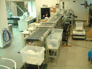
To have an application gathering all the previously referred characteristics, an industrial (sub)system was specified for the transport, classification and distribution of parts. The mechanical system includes equipment such as input/output buffers, conveyer belts, pneumatic cylinders, robot arms and automatic vehicles. This kind of industrial systems (based in conveyers with path switches, etc.) imposes stringent timing and fault-tolerance requirements for the communication network supporting the diverse I/O points (sensors/actuators/servos). Moreover, this kind of system is broadly used in industry, particularly in discrete-part manufacturing applications.
The layout of the manufacturing application is presented in the image below. When a new part arrives (is transported to this subsystem), it must be classified according to a certain criteria and must be distributed to storage buffers or to the next stage of the manufacturing process. This next stage could be further processing (cutting, drilling, etc.) or just transporting a storage buffer to a warehouse. Roller belts and different pneumatic equipment are used to transport and distribute parts to output buffers, according to their type. When output buffers are full, they are moved (either by an automatic vehicle, a robot arm, or an operator) to the respective unload station, in order to be emptied. Considering the classification criteria, at this stage each part is distinguished by its colour.
|
The input buffer (B1) stores black, white and grey (defective) parts, which are sequentially pushed into the roller belt (RB1). SA2 (a swivelling double arm with suction cups) pushes grey parts to RB2. Grey parts go into B5. If this buffer is full or in transit grey parts must circulate around RB1-RB2. When B5 is full, AGV1 moves to U1, for unload operation carried out by a robot arm (R1) and an operator, and then returns to the initial position. White and black parts go into RB3, and black parts are pushed into output buffer (B2). When B2 is full, an operator is warned, in order to unload it. Meanwhile B3 must be used to receive black parts. If both B2 and B3 are non-operational (full or in transit), black parts must circulate in RB1-RB2. White parts go into B4, until it is full or if it is in transit. When B4 is full, AGV2 moves to U2, for unload operation carried out by R2. White parts must circulate around RB1-RB2, if B4 is unavailable.
Next: The Field Trial Network
|
The RFieldbus Project The RFieldbus Field Trial Applications Data streams Videos Photos Extras |